
- HOME
- PRODUCTS
- 2-Wire Transmitter
- 4-Wire Transmitter
- 4-Wire Transmitter (2 Outputs)
- Power Transducer
- Digital Panelmeter
- Big Digital Display (100 mm. Height)
- A.C. Panel Meter
- Data Logger
- Data Acquisition, MODBUS I/O Module (RS-232, RS-485)
- Data Communications
- Wireless Module
- 2-Wire Remote
- Touch Screen
- Calibrator
- Power Protective Relay
- Alarm Module
- Control Module
- PLC Analog Input-Output
- Accessories
- APPLICATIONS
- SUPPORTS
- CONTACT US
Alarm Module
PL2000: Pilot Lamp
|
|
- 10 LED Lamps
- 3 Color Selectable (Red, Blue, Green) - Programmable Flashing |
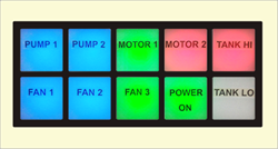
General Features and Benefits:
10 LED Lamps
3 Color Selectable (Red, Blue, Green)
Programmable Flashing
Pilot Lamp PL2000 It features 10 LED lamps capable of displaying three selectable colors; examples of applications include indicating machine operating status or alarm conditions.
 |
 |
|
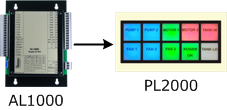
Displays the alarm status received from the Alarm Annunciator AL1000. |
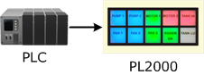
The PLC sends a digital output signal for control. |
Note: Customers can print text on the dial according to their own desired design. (Text in the image: Angsana New, Size: 24 px)
Warranty:
5 years
 ภาษาไทย
AL2000: Alarm Annunciator
 |
- 10 Channels Input
- LED Display - Siren Relay Output - First Alarm Detect - Expandable Input Channel |
General Features and Benefits:
10 Channels Input
LED Display
Siren Relay Output
First Alarm Detect
Expandable Input Channel
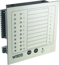
Alarm Annunciator AL2000 This device detects, displays, and issues warnings when an alarm condition arises within a system. Control systems typically monitor various parameters-such as temperature, pressure, and motor speed-to prevent potential damage. If an abnormality occurs, the monitoring system alerts the operator so that corrective action can be taken.
Sometimes, an alarm triggered at one point causes subsequent alarms at other points in close succession, making it difficult for operators to identify the root cause of the fault. To address this, the AL2000 is designed so that the alarm LED for the channel that triggers first flashes rapidly, while the alarm LEDs for subsequent channels flash slowly. The siren relay activates when any alarm occurs and deactivates when the "Reset" button is pressed; however, the alarm LED remains steadily lit until the fault is resolved, at which point the LED turns off.
In cases where the alarm system requires more than 10 input channels, AL2000 units can be interconnected to expand the number of input channels.
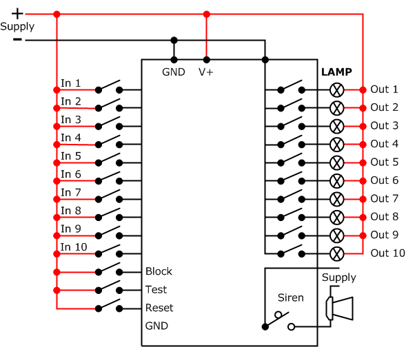
| Input Status | First Alarm | Subsequence Alarm | Siren |
| First Alarm | Quick Flash | OFF | ON |
| Subsequence Alarm | Quick Flash | Slow Flash | ON |
| Return to Normal | Steady - ON | Steady - ON | OFF |
| Reset | OFF | OFF | OFF |
| Test | Slow Flash | Slow Flash | ON |

Warranty:
5 years
TM395: Thermistor Trip Relay
 |
- Prevent Motor/Transformer damage from
high-temp - PTC Thermistor Sensor - Two Level Protection (Alarm and Trip) |
General Features and Benefits:
Prevent Motor/Transformer damage from high-temp
PTC Thermistor Sensor
Two Level Protection (Alarm and Trip)
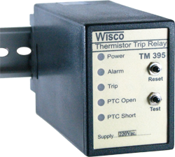
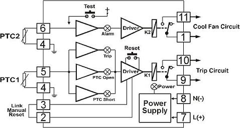
Thermistor Trip Relay TM395 This device protects electrical equipment-such as motors and transformers-from damage caused by excessive temperatures (over-temperature conditions) by operating in conjunction with a PTC thermistor sensor. PTC sensors exhibit low resistance when the temperature is below the nominal operating temperature; however, when the temperature exceeds this threshold, the resistance increases sharply. Since PTC sensors are available in various types based on their nominal operating temperatures, the specific sensor selected determines the temperature at which the relay activates. The TM395 supports the use of two PTC sensor sets and operates as follows:
-
When the temperature of PTC1 is below the nominal operating temperature, Relay K1 turns ON; however, when the temperature exceeds this level, the relay turns OFF. When the temperature subsequently drops below the nominal operating temperature, the relay turns ON if the TM395 is in Auto Reset mode; if it is in Manual Reset mode, the Reset button must be pressed to turn the relay ON. Additionally, if the PTC sensor experiences a short circuit or an open circuit, the relay turns OFF.
- When the temperature of PTC2 falls below the nominal operating temperature, Relay K2 turns OFF; when the temperature rises above the nominal operating temperature, Relay K2 turns ON. When the temperature subsequently drops below the nominal operating temperature, Relay K2 turns OFF; however, a switch-off delay can be configured for Relay K2. If this delay function is enabled, Relay K2 will not turn OFF until the set time has elapsed (selectable options: 5, 10, or 20 minutes). Relay K2 is suitable for connection to alarm systems or cooling fans.
Warranty:
5 years
TM495: Thermistor Trip Relay
 |
- Prevents Damage To Motors Or Transformers Caused By High Temperatures - PTC Thermistor Sensor - Sensor Fail Detection |
General Features and Benefits:
ป้องกัน Motor หรือ Transformer เสียหาย เนื่องจากอุณหภูมิสูง
PTC Thermistor Sensor
Sensor Fail Detection
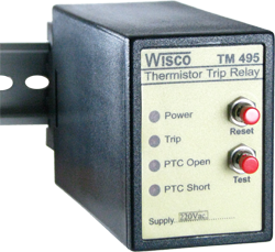
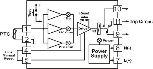
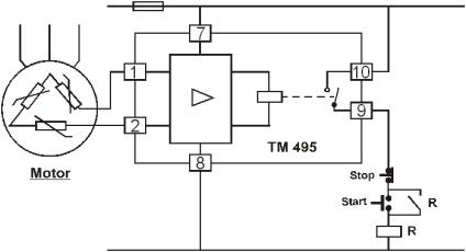
Thermistor Trip Relay TM495 This device protects electrical equipment-such as motors and transformers-from damage caused by high temperatures (over-temperature conditions) by operating in conjunction with a PTC thermistor sensor. PTC sensors exhibit low resistance when the temperature is below the nominal operating temperature; however, when the temperature exceeds this threshold, the resistance increases sharply. Since PTC sensors are available in various types based on their nominal operating temperatures, the specific sensor selected determines the temperature at which the relay activates. The TM495 operates as follows:
When the PTC temperature is below the Nominal Operating Temperature (NOT), Relay K1 turns ON; however, when the temperature exceeds the NOT, the relay turns OFF. When the temperature subsequently drops below the NOT, the relay turns ON if the TM495 is in Auto Reset mode; conversely, if it is in Manual Reset mode, the Reset button must be pressed to turn the relay ON. Additionally, the relay will turn OFF if the PTC sensor experiences a short circuit or an open circuit.
Warranty:
5 years
DA95: DC Alarm
 |
- Two alarm set points
- DC. current or voltage input - SPDT relay output - 24 VDC supply for 2-wire transmitter |
General Features and Benefits:
Two alarm set points
DC. current or voltage input (4-20 mA, 1-5 VDC, 0-10 VDC)
SPDT relay output
24 VDC supply for 2-wire transmitter
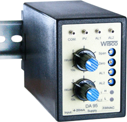
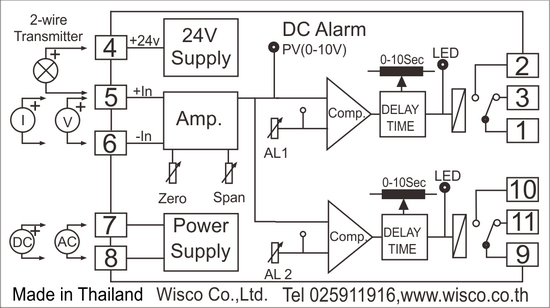
DC Alarm DA 95 This device accepts voltage or current input signals and allows for the configuration of two alarm setpoints. It utilizes a multi-turn potentiometer for precise setpoint adjustment, and each alarm channel can be configured as either a high or low alarm. Additionally, it features a 24 VDC power supply to power external devices, such as 2-wire transmitters. The DA95 is designed as a plug-in module for an 11 pin socket, facilitating easy installation and replacement.
How to Configure Setpoints and Operation for the DA95
DA95 Input signals received via the +in and -in terminals are compared against the alarm setpoints (SET1, SET2). If the alarm mode is set to "Low alarm," the relay turns "ON" when the input value falls below the alarm setpoint; if set to "High alarm," the relay turns "ON" when the input value exceeds the alarm setpoint.
Zero and Span Adjustment
Use a digital voltmeter to measure at the "PV" (process value) test point, connecting the voltmeter's negative terminal to the "COM" test point; a PV reading of 10 VDC corresponds to 100% of the input signal, and 0 VDC corresponds to 0% of the input signal.
-
Apply a 0% input signal and adjust the "Zero" knob until the voltmeter reads 0 VDC.
-
Apply a 100% input signal and adjust the "Span" knob until the voltmeter reads 10 VDC.
- Repeat the adjustments described in steps 1 and 2, alternating between them, until the Zero and Span values no longer change. (Typically, Zero and Span are calibrated according to the input range specified on the dial.)
Setting The Alarm Setpoint
The DA95 allows for the configuration of two alarm setpoints. Test points SET1 and SET2 are used to measure these setpoint values, where 10 VDC corresponds to 100% of the input and 0 VDC corresponds to 0% of the input. Measure the voltage at points "SET1" and "SET2" using a digital voltmeter by connecting the voltmeter's negative terminal to the "COM" terminal. For example, to set the alarm at 60% of the input, adjust the "SET" value to 6 VDC.
Warranty:
5 years
AL100: LINE Notify Alarm System
|
|
- 24 Alarm Digital Inputs
- Sending Alarm to LINE Notify, LINE Messaging API, Telegram, E-Mail - Programmable Alarm Message - Buffer 100 Alarm Message (Network Fail) - Support Passive POE |
General Features and Benefits:
24 Alarm Digital Inputs
Sending Alarm to LINE Notify, LINE Messaging API, Telegram, E-Mail
Programmable Alarm Message
Buffer 100 Alarm Message (Network Fail)
Support Passive POE
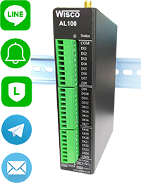
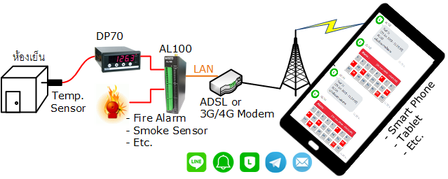
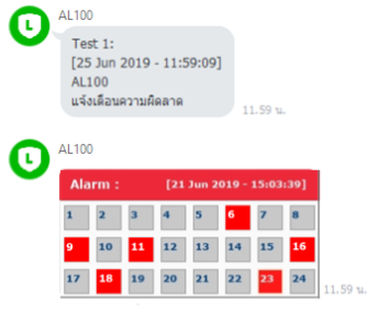
 Notify Alarm System AL100 Upon receiving an external alarm signal via the Digital Input, the AL100 transmits notification messages to pre-configured destinations, including LINE Notify, LINE Messaging API, Telegram, email, and a database server (Wisserv). Users can customize these notification messages via a web browser interface.
The AL100 can receive alarm signals from various devices, such as PLCs, contact switches, and proximity sensors. If a network connection is unavailable, the AL100 can buffer up to 100 alarm events. Once the network connection is restored, the AL100 automatically transmits the stored alarm data to LINE Notify, LINE Messaging API, Telegram, email, and databases.
Warranty:
5 years
AL200 : Modbus Line Alarm System
|
|
- Sending Alarm to LINE Messaging API, Telegram, E-Mail
- Programmable Alarm Message and Pictures - Buffer 100 Alarm Message (Network Fail) - Keep 80 Data as Tag (Max. 128 tags Option) - Serial Interface (RS232/485 and Ethernet Interface (LAN or WI-FI) - Support MODBUS ASCII, RTU, TCP/IP - Provides MODBUS TCP Server - Remappable MODBUS Register Address |
General Features and Benefits:
Sending Alarm to LINE Messaging API, Telegram, E-Mail
Programmable Alarm Message and Pictures
Buffer 100 Alarm Message (Network Fail)
Keep 80 Data as Tag (Max. 128 tags Option)
Serial Interface (RS232/485 and Ethernet Interface (LAN or WI-FI)
Support MODBUS ASCII, RTU, TCP/IP
Provides MODBUS TCP Server
Remappable MODBUS Register Address
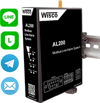
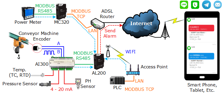
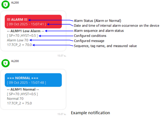
Modbus Line Alarm System AL200 It is a device designed to send notification messages (Alarm) to LINE Messaging API, Telegram, E-Mail or Wisserv (Database). When the measured value is greater than or less than the pre-programmed value, the user can program a notification message and image through various web browsers.
In case the alarm cannot be sent, which may be due to a network problem (Network Failed), the AL200 can hold the data of up to 100 alarms. When the network connection is re-established, the AL200 will automatically send the held alarm data.
AL200 reads values from devices communicating via Modbus Protocol ASCII/RTU (RS232/485) and Modbus TCP/IP (LAN, WiFi) such as PLC, Power Meter, Analog Module, RTU, etc.
AL200 can also send the collected data to other devices for further reading via the MODBUS TCP/IP protocol. It can also change the register address (Remappable MODBUS Register Address) by rearranging it as desired.
Warranty:
5 years
AL200 : Modbus Line Alarm System
|
|
- ส่งข้อความแจ้งเตือนไปยัง LINE Messaging API, Telegram
หรือ E-Mail - กำหนดข้อความแจ้งเตือนและรูปภาพล่วงหน้า - พักข้อความแจ้งเตือนสูงสุด 100 ข้อความ ในกรณีที่เชื่อมต่อกับ เครือข่ายไม่ได้ - อ่านค่าวัดได้ 80 Tag (Max. 128 tags Option) - อ่านค่าวัดผ่านทางพอร์ต Serial (RS232/485) และ Ethernet (LAN/WIFI) - รองรับการสื่อสาร Modbus Protocol (ASCII, RTU, TCP/IP) - ส่งข้อมูลต่อไปยังอุปกรณ์อื่นๆผ่านทาง Modbus TCP Server - เปลี่ยนแปลงหมายเลขของ MODBUS Register ได้ |
General Features and Benefits:
ส่งข้อความแจ้งเตือนไปยัง LINE Messaging API, Telegram หรือ E-Mail
กำหนดข้อความแจ้งเตือนและรูปภาพล่วงหน้า
พักข้อความแจ้งเตือนสูงสุด 100 ข้อความ ในกรณีที่เชื่อมต่อกับเครือข่ายไม่ได้
อ่านค่าวัดได้ 80 Tag (Max. 128 tags Option)
อ่านค่าวัดผ่านทางพอร์ต Serial (RS232/485) และ Ethernet (LAN/WIFI)
รองรับการสื่อสาร Modbus Protocol (ASCII, RTU, TCP/IP)
ส่งข้อมูลต่อไปยังอุปกรณ์อื่นๆผ่านทาง Modbus TCP Server
เปลี่ยนแปลงหมายเลขของ MODBUS Register ได้
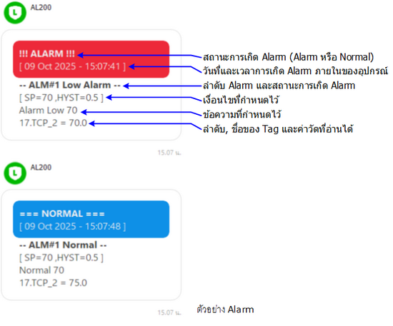
Modbus Line Alarm System AL200 เป็นอุปกรณ์ที่ถูกออกแบบมาเพื่อให้ส่งข้อความการแจ้งเตือน (Alarm) ไปยัง LINE Messaging API, Telegram, E-Mail หรือ Wisserv (Database) เมื่อค่าวัดมีค่า มากกว่าหรือต่ำกว่า ค่าที่กำหนดไว้ ซึ่งถูกโปรแกรมไว้ล่วงหน้า โดยผู้ใช้งานสามารถโปรแกรมข้อความการแจ้งเตือนและรูปภาพผ่านทางหน้าเว็บบราวเซอร์ต่างๆ
ในกรณีที่ไม่สามารถส่ง Alarm ได้นั้น ซึ่งอาจจะเกิดจากเครือข่ายมีปัญหา (Network Failed) AL200 สามารถพักข้อมูลการเกิด Alarm ได้สูงสุด 100 Alarm เมื่อเชื่อมต่อกับเครือข่ายได้อีกครั้ง AL200 จะทำการส่งข้อมูล Alarm ที่พักไว้โดยอัตโนมัติ
AL200 อ่านค่าจากอุปกรณ์ที่สื่อสารด้วย Modbus Protocol ASCII/RTU (RS232/485) และ Modbus TCP/IP (LAN, WiFi) เช่น PLC, Power Meter, Analog Module, RTU ฯลฯ
AL200 ยังสามารถส่งข้อมูลที่รวบรวมไว้ให้กับอุปกรณ์อื่นๆมาอ่านเพื่อนำค่าไปใช้งานต่อได้อีกด้วย ผ่านทางโปรโตคอล MODBUS TCP/IP อีกทั้งยังสามารถเปลี่ยนตำแหน่งของรีจีสเตอร์ (Remappable MODBUS Register Address) โดยให้จัดเรียงตำแหน่งใหม่ได้ตามต้องการ
Warranty:
5 years
 English
AL100: LINE Notify Alarm System
|
|
- 24 Alarm Digital Inputs
- Sending Alarm to LINE Notify, LINE Messaging API, Telegram, E-Mail - Programmable Alarm Message - Buffer 100 Alarm Message (Network Fail) - Support Passive POE |
General Features and Benefits:
24 Alarm Digital Inputs
Sending Alarm to LINE Notify, LINE Messaging API, Telegram, E-Mail
Programmable Alarm Message
Buffer 100 Alarm Message (Network Fail)
Support Passive POE
Notify Alarm System AL100 เมื่อได้รับสัญญาณการเกิด Alarm จากภายนอกผ่านทาง Digital Input AL100 จะส่งข้อความแจ้งเตือนไปยัง LINE Notify, LINE Messaging API, Telegram, E-Mail และ Database Server (Wisserv) ซึ่งถูกโปรแกรมไว้ล่วงหน้า การโปรแกรมข้อความการแจ้งเตือนผู้ใช้สามารถโปรแกรมเองได้ผ่านทางหน้าเว็บบราวเซอร์
AL100 สามารถรับสัญญาณ Digital การเกิด Alarm ได้จากอุปกรณ์หลายแบบ เช่น PLC, Contact Switch, Proximity Sensor ในกรณีที่ไม่สามารถเชื่อมต่อกับระบบ Network ได้นั้น AL100 สามารถพักข้อมูลการเกิด Alarm ได้ 100 Alarm เมื่อเชื่อมต่อกับระบบ Network ได้อีกครั้ง AL100 จะทำการส่งข้อมูล Alarm ที่พักไว้ไปยัง LINE Notify, LINE Messaging API, Telegram, E-Mail และ Database โดยอัตโนมัติ
Warranty:
5 years
RC38: GSM Alarm
 |
- 4 Analog Channels High-Low Alarm
- 2 Digital (Counter or Status) Alarm - Programmable SMS Message - Two Relay Output Control VIA SMS - Read Out VIA SMS - Built-in 3G Modem (UMTS/HSDPA) |
General Features and Benefits:
4 Analog Channels High-Low Alarm
2 Digital (Counter or Status) Alarm
Programmable SMS Message
Two Relay Output Control VIA SMS
Read Out VIA SMS
Built-in 3G Modem (UMTS/HSDPA)
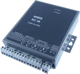
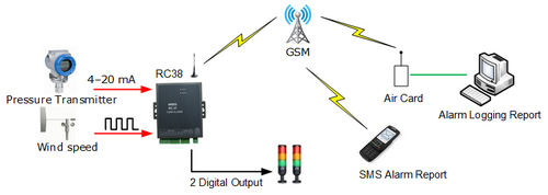
GSM Alarm RC38 When alarm happen RC38 will send SMS to the destination which was pre programmed. The alarm conditions as the following
1. Analog Input Alarm Each analog input can program 2 alarm levels.
2. Digital Input Alarm When digital input change status
3. More than this we can send SMS to comtrol (on - off) 2 internal relays of RC38. And can send SMS to read the value of analog input
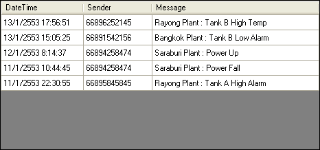
Example of SMS Report
Warranty:
5 years
