
- HOME
- PRODUCTS
- 2-Wire Transmitter
- 4-Wire Transmitter
- 4-Wire Transmitter (2 Outputs)
- Power Transducer
- Digital Panelmeter
- Big Digital Display (100 mm. Height)
- A.C. Panel Meter
- Data Logger
- Data Acquisition, MODBUS I/O Module (RS-232, RS-485)
- Data Communications
- Wireless Module
- 2-Wire Remote
- Touch Screen
- Calibrator
- Power Protective Relay
- Alarm Module
- Control Module
- PLC Analog Input-Output
- Accessories
- APPLICATIONS
- SUPPORTS
- CONTACT US
Power Protective Relay
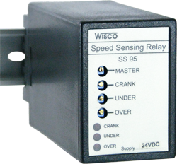
SS95: Speed Sensing Relay
 |
- Magnetic pick-up input
- 3 Speed set point - Output relay contact |
General Features and Benefits:
Magnetic pick-up input
3 Speed set point
Output relay contact
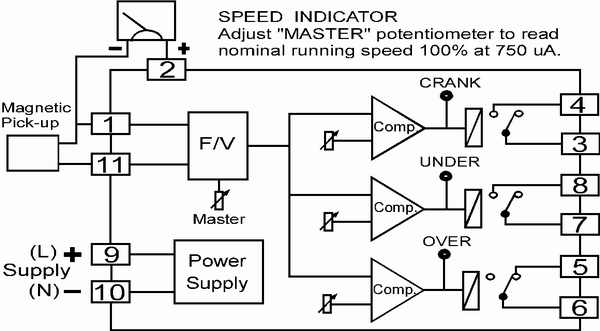
Speed Sensing Relay SS95 provides 3 user adjustable trip levels with LED relay state indication and a speed indicator output signal. Trip functions provided are
CRANK disengages the crank starter
UNDER SPEED energises protection or underspeed alarm
OVER SPEED alarms or trips on overspeed
A magnetic pick-up, situated close to the engine flywheel, produces a high frequency pulse train directly proportional to the number of teeth passing it. The frequency of these pulse is converted to an analogue signal which is used to provide both engine speed indication and the signal to the trip circuitry.
Warranty:
5 years
 ภาษาไทย
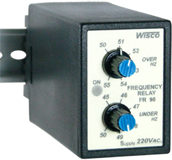
FR95: Frequency Relay
 |
- Over-under frequency Protection
- Output relay SPDT, 250V, 3A - LED indicate relay status - Signal output for panel meter display |
General Features and Benefits:
Over-under frequency Protection
Output relay SPDT, 250V, 3A
LED indicate relay status
Signal output for panel meter display
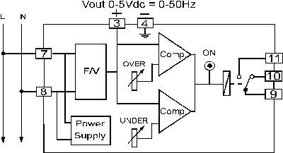
The Frequency Relay FR95 is designed to monitor the system frequency. When the frequency moves outside the setpoint limit the relay will operate giving an alarm or tripping signal. Since speed is propotional to frequency, it can be used to protect A.C. generator plant against overspeed or underspeed.
Warranty:
5 years
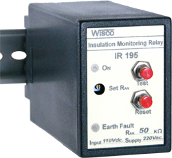
IR195: Insulation Monitoring Relay
 |
- Insulation Monitor 10 to 200 KΩ
- SPDT Relay Contact Output. - Earth Fault LED Indicator |
General Features and Benefits:
Insulation Monitor 10 to 200 KΩ
SPDT Relay Contact Output.
Earth Fault LED Indicator
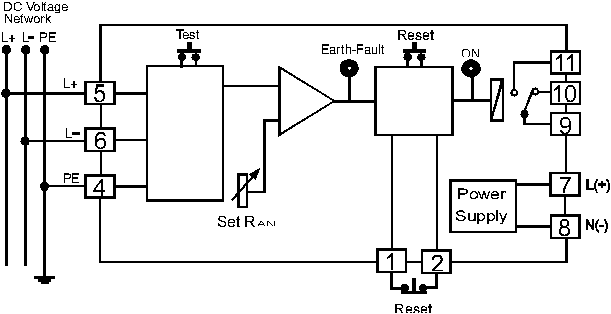
The Insulation Monitoring Relay IR195 measures the network insulation resistance of ungrounded DC current networks to earth. Symmetrical earth faults are not detected, however this is of no significance for the fault conditions normally encountered. Threshold value RAN is factory set and non-variable. The IR 195 works according to the contact opening principle. Application of the aux. voltage causes the output relay to switch to the work position and a LED marked "ON" is lit, indicating that network insulation resistance RE>RAN. If the network insulation resistance drops below RAN the LED (ON) extinguishes, another LED marked "earth fault" is lit and the output relay deenergizes. With a jumper between terminal "1" and "2" IR 195 is programmed for memory, without link for hysteresis function. This link may be replaced by an external NC contact reset switch Correct functioning of the relay can be verified with a built-in test key.
Warranty:
5 years
CR95: Current Relay
 |
- Prevents Damage To The Motor And Load.
- Protects Against Overcurrent Or Undercurrent. - Adjustable Time Delay0 - 10 Seconds. - Startup Delay Time Can Be Set From 0 To 30 - SPDT Relay Output |
General Features and Benefits:
ป้องกันความเสียหายของ Motor และ Load
ป้องกันกระแสเกินหรือกระแสตก
ตั้งหน่วงเวลาได้ 0 -10 วินาที
ตั้งหน่วงเวลาขณะสตาร์ทได้ 0 - 30 วินาที
SPDT Relay Output
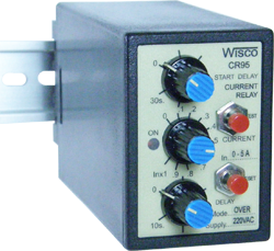
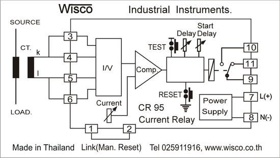
Current Relay CR 95 This electronic device is designed to protect against over-current or under-current conditions. The current relay monitors the electrical current; if the current exceeds the preset threshold, the relay activates and a red LED indicator lights up. Current settings are adjusted via the “CURRENT” knob, while the relay's operation delay can be set between 0 and 10 seconds using the “DELAY” knob. Additionally, a specific start-up delay (“START DELAY”) of 0 to 30 seconds can be configured to prevent the relay from triggering due to high starting currents. This current relay is suitable for protecting various types of electrical equipment, such as:
-
It provides motor overload protection; the current relay is more sensitive than standard bimetallic overload units, thereby offering superior protection against damage to the motor and its load.
- In certain applications, an under-current condition can lead to damage-such as a heater burnout, a broken drive belt, or a pump running dry (without fluid flow). A current relay can be used to prevent such damage.
Warranty:
5 years
AR95: Asymmetry Relay
 |
- Protects Against Phase Loss And Phase Reversal - Protects Against Undervoltage Or Overvoltage - Protects Against Phase Unbalance - Time Delay Adjustable From 0 To 10 Seconds. - Unbalance Setting Range 5 - 15 % |
General Features and Benefits:
ป้องกันเฟสขาด, ต่อสลับเฟส
ป้องกันแรงดันไฟฟ้าตกหรือเกิน
ป้องกันเฟสไม่สมดุล (phase unbalance)
ตั้งหน่วงเวลาได้ 0 - 10 วินาที
ตั้ง Unbalance ได้ 5 - 15%
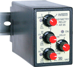
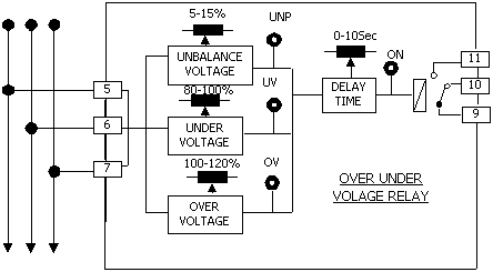
Asymmetry Relay AR95 This device monitors for 3 phase voltage imbalances, incorrect phase sequences, and undervoltage or overvoltage conditions (based on the 3 phase average). Under normal operating conditions, the relay is energized (ON) and the red LED is illuminated. If a voltage imbalance exceeds the preset threshold, the relay de-energizes (OFF); a time delay of 0-10 seconds can be configured for this de-energization using the "Delay" adjustment knob. The device serves to protect against unbalanced loads, phase loss (incomplete 3 phase supply), phase reversal, undervoltage, and overvoltage.
Warranty:
5 years
VR195: Voltage Relay
 |
- ป้องกันแรงดันไฟฟ้าเกินหรือตก
- ช่วยลดความเสียหายของอุปกรณ์ไฟฟ้าเนื่องจาก แรงดันไฟฟ้าผิดปกติ - สามารถตั้งหน่วงเวลาได้ 0-10 วินาที - มี LED แสดงสภาวะแรงดันไฟฟ้าตกหรือเกิน |
General Features and Benefits:
ป้องกันแรงดันไฟฟ้าเกินหรือตก
ช่วยลดความเสียหายของอุปกรณ์ไฟฟ้าเนื่องจากแรงดันไฟฟ้าผิดปกติ
สามารถตั้งหน่วงเวลาได้ 0-10 วินาที
มี LED แสดงสภาวะแรงดันไฟฟ้าตกหรือเกิน
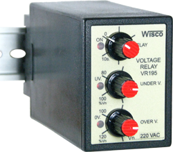
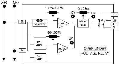
The Voltage Relay monitors the input voltage. The relay is energized and red LED. Lights up if the voltage is within the set-point limit. When the measured voltage moves outside the set-point limit, the relay will be deenergized. It is also fitted with an adjustable time delay to eliminate voltage fluctuations. The Voltage Relay can be used to protect against under or over voltage, to start up standby generators, to operate mains failure units, for switching standby hybrid supplies, protecting computer supplies and similar where close regulation is required.
Warranty:
5 years
VR95: Voltage Relay
 |
- ป้องกันแรงดันไฟฟ้าเกินหรือตก - สามารถตั้งหน่วงเวลาได้ 0 - 10 วินาที - มี LED แสดงสภาวะของ Relay - มี LED แสดงสภาวะแรงดันไฟฟ้าตกหรือเกิน |
General Features and Benefits:
ป้องกันแรงดันไฟฟ้าเกินหรือตก
สามารถตั้งหน่วงเวลาได้ 0 - 10 วินาที
มี LED แสดงสภาวะของ Relay
มี LED แสดงสภาวะแรงดันไฟฟ้าตกหรือเกิน
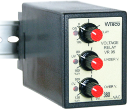
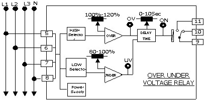
Voltage Relay VR95 The Voltage Relay monitors the average of input voltage. The relay is energized and red LED. Lights up if the voltage is within the set-point limit. When the measured voltage moves outside the set-point limit, the relay will be deenergized. It is also fitted with an adjustable time delay to eliminate voltage fluctuations. The Voltage Relay can be used to protect against under or over voltage, to start up standby generators, to operate mains failure units, for switching standby hybrid supplies, protecting computer supplies and similar where close regulation is required.
Warranty:
5 years
RR20: Reverse Power Relay
 |
- Motoring protection
- Adjustable time delay - Easy to install - Power signal output for indicator |
General Features and Benefits:
Motoring protection
Adjustable time delay
Easy to install
Power signal output for indicator
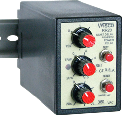
Reverse Power Relay RR20 monitors the power flow at the terminals of an ac-generator. The relay operates when the real power flow in a given direction exceeds predetermined limits. This Protects the machine against motoring due to loss of prime mover torque. A time delay is incorporated to avoid tripping due to ransients such as those encountered due to load rejection or during synchronization. RR20 also have power output signal for power indicator meter.
Setting and Testing
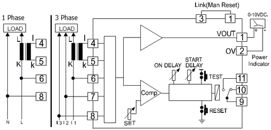
- Wiring as show on Diagram. Beware: signal from CT should really come from CT of Phase L1 and Polarity of CT should wiring as show in diagram
- Load D.C. Voltage at Volt (1) should be +, 0 V (2) if Volt is negative it mean Polarity of CT is switch between l and k
- In order to test Reverse Power Relay. Switch line of CT then Volt should be negative and Relay should be “ON” status and LED of “TRIP” is light up.
- “ON DELAY” button is for setting delay time of Relay ON when Reverse Power is more than set up value
- “START DELAY” button is for setting up delay time of Relay ON only wen start powering L1, L2 and L3
Warranty:
5 years
ER95: Ground - Fault Relay
 |
- ป้องกันกระแสรั่วลง Ground
- ตั้งหน่วงเวลาได้ 0 - 1 sec |
General Features and Benefits:
ป้องกันกระแสรั่วลง Ground
ตั้งหน่วงเวลาได้ 0 - 1 sec
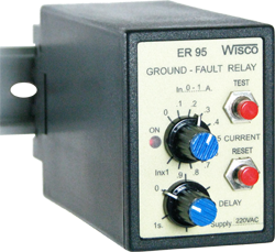
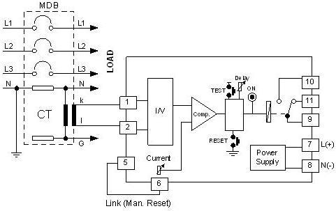
Ground-Fault Relay ER95 is an equipment for detect Ground-Fault Current. It operate with external CT/5A (Current Transformer) It can operate in 2 mode as the following.
Auto Reset Mode
When Ground-Fault Current is over “Current” Setpoint. The internal relay will on and terminal “9” will break from terminal “11” and connect with terminal “10”. When Ground-Fault Current drop below “Current” Setpoint. The internal relay will off and the contact will switch back to the first stage.
Manual Reset Mode
to operate in this mode the cable have to short between terminal “5” and terminal “6”. When Ground-Fault Current is over “Current” Setpoint. The Internal relay will on but when Ground-Fault Current drop below “Current” Setpoint the relay will not off you have to push the “Reset” button the relay will off.
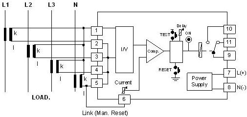
The scale of “Current” Setting knob is depend on CT Ration that connect with ER95 as the following formula
"Current" Setting = (Ground - Fault Current) / CT Ratio
Example using CT 500/5A and want to set Ground-Fault Current trip at 30A. From the formular
"Current" Setting = (30 x 5) / 500 = 0.3
From the calculation you have to set “Current” knob at 0.3
Warranty:
5 years
SS95: Speed Sensing Relay
|
|
- Magnetic pick-up input
- 3 Speed set point - Output relay contact |
General Features and Benefits:
Magnetic pick-up input
3 Speed set point
Output relay contact
Speed Sensing Relay SS95 provides 3 user adjustable trip levels with LED relay state indication and a speed indicator output signal. Trip functions provided are
CRANK disengages the crank starter
UNDER SPEED energises protection or underspeed alarm
OVER SPEED alarms or trips on overspeed
A magnetic pick-up, situated close to the engine flywheel, produces a high frequency pulse train directly proportional to the number of teeth passing it. The frequency of these pulse is converted to an analogue signal which is used to provide both engine speed indication and the signal to the trip circuitry.
Warranty:
5 years
 English