- HOME
- PRODUCTS
- 2-Wire Transmitter
- 4-Wire Transmitter
- 4-Wire Transmitter (2 Outputs)
- Power Transducer
- Digital Panelmeter
- Big Digital Display (100 mm. Height)
- A.C. Panel Meter
- Data Logger
- Data Acquisition, MODBUS I/O Module (RS-232, RS-485)
- Data Communications
- Wireless Module
- 2-Wire Remote
- Touch Screen
- Calibrator
- Power Protective Relay
- Alarm Module
- Control Module
- PLC Analog Input-Output
- Accessories
- APPLICATIONS
- SUPPORTS
- CONTACT US
RR20: Reverse Power Relay
 |
- Motoring protection
- Adjustable time delay - Easy to install - Power signal output for indicator |
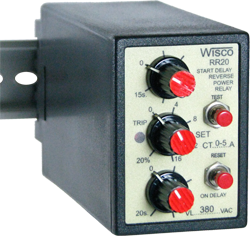
Reverse Power Relay RR20 monitors the power flow at the terminals of an ac-generator. The relay operates when the real power flow in a given direction exceeds predetermined limits. This Protects the machine against motoring due to loss of prime mover torque. A time delay is incorporated to avoid tripping due to ransients such as those encountered due to load rejection or during synchronization. RR20 also have power output signal for power indicator meter.

Setting and Testing
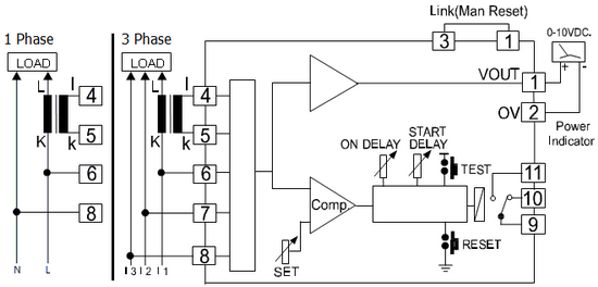
- Wiring as show on Diagram. Beware: signal from CT should really come from CT of Phase L1 and Polarity of CT should wiring as show in diagram
- Load D.C. Voltage at Volt (1) should be +, 0 V (2) if Volt is negative it mean Polarity of CT is switch between l and k
- In order to test Reverse Power Relay. Switch line of CT then Volt should be negative and Relay should be “ON” status and LED of “TRIP” is light up.
- “ON DELAY” button is for setting delay time of Relay ON when Reverse Power is more than set up value
- “START DELAY” button is for setting up delay time of Relay ON only wen start powering L1, L2 and L3
