
- HOME
- PRODUCTS
- 2-Wire Transmitter
- 4-Wire Transmitter
- 4-Wire Transmitter (2 Outputs)
- Power Transducer
- Digital Panelmeter
- Big Digital Display (100 mm. Height)
- A.C. Panel Meter
- Data Logger
- Data Acquisition, MODBUS I/O Module (RS-232, RS-485)
- Data Communications
- Wireless Module
- 2-Wire Remote
- Touch Screen
- Calibrator
- Power Protective Relay
- Alarm Module
- Control Module
- PLC Analog Input-Output
- Accessories
- APPLICATIONS
- SUPPORTS
- CONTACT US
TI20: Temperature Indicator
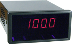 |
- 3 ½ digits LED display
- Thermocouple or RTD Sensor - 4-20 mA, 0-10 VDC, Analog Output |
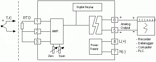
Temperature Indicator TI20 This device displays temperature readings numerically. It is compatible with thermocouple or RTD sensors and features an analog output for connection to a recorder or PLC.
How to Calibrate the Display
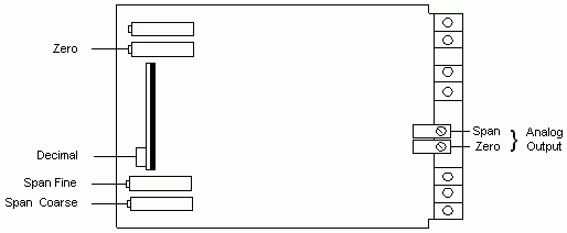
Open the front panel to reveal the “ZERO” and “SPAN” adjustment knobs, arranged as shown in the figure.
- Apply an input signal at 0% of the input range. Adjust the “ZERO” knob until the display shows the minimum temperature of the input range.
- Apply an input signal at 100% of the input range. Adjust the “SPAN” control until the display shows the maximum temperature of the input range.
- Repeat steps 1 and 2 alternately until the temperature value can be displayed according to the input range.
How to Calibrate Analog Output
The “ZERO” and “SPAN” adjustment knobs for calibrating the analog output are located on the back of the unit.
- Apply an input signal at 0% of the input range and adjust the “ZERO” control until the analog output reaches the minimum value of the output range.
- Apply an input signal at 100% of the input range. Adjust the “SPAN” control until the analog output reaches the maximum value of the output range.
- Repeat steps 1 and 2, alternating between them, until the desired analog output value is obtained.
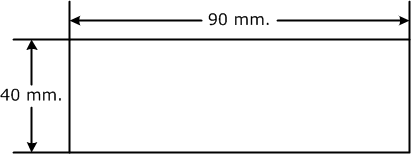
Panel Cutout
 ภาษาไทย