- HOME
- PRODUCTS
- 2-Wire Transmitter
- 4-Wire Transmitter
- 4-Wire Transmitter (2 Outputs)
- Power Transducer
- Digital Panelmeter
- Big Digital Display (100 mm. Height)
- A.C. Panel Meter
- Data Logger
- Data Acquisition, MODBUS I/O Module (RS-232, RS-485)
- Data Communications
- Wireless Module
- 2-Wire Remote
- Touch Screen
- Calibrator
- Power Protective Relay
- Alarm Module
- Control Module
- PLC Analog Input-Output
- Accessories
- APPLICATIONS
- SUPPORTS
- CONTACT US
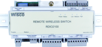
RDIO2100: Remote Wireless Switch
 |
- Control 8 Digital Input / Output
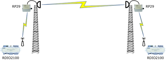
- Long Distance 700 m. - No Wiring (RF Link) |
Remote Wireless Switch RDIO2100 is remote wireless switch. It use for ON/OFF electronic device for long distance. RDIO2000 is radio frequency device so it is cost saving and No need for wiring

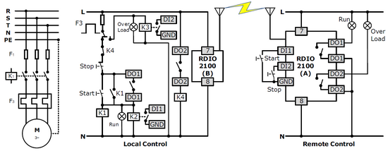
When digital input of first RDIO2000 is “ON” then digital output of the second RDIO2000 is “ON”. Di1 of RDIO2000 (1) is “ON” then Do1 of RDIO2000 (2) is “NO”.

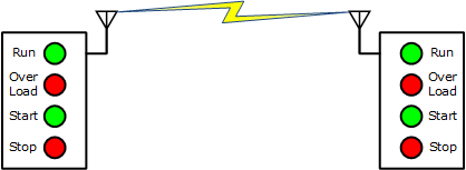
Show the Working Status of the Machine Through PL2000.

Remote Motor Control Application (4 Sets Max.)

NOTE: When turn on device Power LED is “on” and RDIO2100 start to connecting to its pair. Connecting status indicate by LED light, Quickly blink is mean “connected” and slowly blink is mean “connecting fail”
| DIP Switch 1 | Last Status Mode |
| OFF | Digital Output OFF |
| ON | Hold Digital Output |
There are 2 required setting
-
Status of DO when is no connecting
-
Delay time for time out, if there is no response until delay time is run out RDIO2100
will show connecting error. For example. If time delay time for time out is set at 5 seconds, after sending connection it will wait or 5 seconds if there is no response within 5 seconds error is occur. Table below is show dip switch for setting delay time
| Delay Time (Sec.) | DIP Switch 4 | DIP Switch 3 | DIP Switch 2 |
| 5 | OFF | OFF | OFF |
| 10 | OFF | OFF | ON |
| 15 | OFF | ON | OFF |
| 20 | OFF | ON | ON |
| 25 | ON | OFF | OFF |
| 30 | ON | OFF | ON |
| 35 | ON | ON | OFF |
| 40 | ON | ON | ON |
Table below is show dip switch for setting amount of repeater in the network
| Dip Switch | จำนวน Repeater | ||
| 6 | 7 | 8 | |
| OFF | OFF | OFF | 1 |
| ON | OFF | OFF | 2 |
| OFF | ON | OFF | 3 |
| ON | ON | OFF | 4 |
| OFF | OFF | ON | 5 |
| ON | OFF | ON | 6 |
| OFF | ON | ON | 7 |
| ON | ON | ON | 8 |
*** in case of no repeater Dip switch 6, 7 and 8 should be set at OFF position

