
- HOME
- PRODUCTS
- 2-Wire Transmitter
- 4-Wire Transmitter
- 4-Wire Transmitter (2 Outputs)
- Power Transducer
- Digital Panelmeter
- Big Digital Display (100 mm. Height)
- A.C. Panel Meter
- Data Logger
- Data Acquisition, MODBUS I/O Module (RS-232, RS-485)
- Data Communications
- Wireless Module
- 2-Wire Remote
- Touch Screen
- Calibrator
- Power Protective Relay
- Alarm Module
- Control Module
- PLC Analog Input-Output
- Accessories
- APPLICATIONS
- SUPPORTS
- CONTACT US
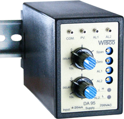
DA95: DC Alarm
 |
- Two alarm set points
- DC. current or voltage input - SPDT relay output - 24 VDC supply for 2-wire transmitter |
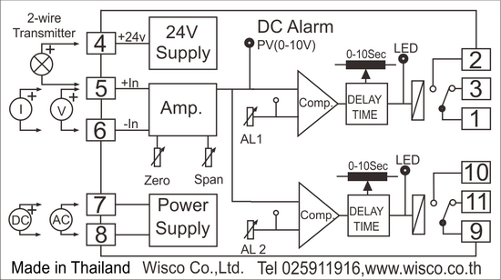
DC Alarm DA 95 This device accepts voltage or current input signals and allows for the configuration of two alarm setpoints. It utilizes a multi-turn potentiometer for precise setpoint adjustment, and each alarm channel can be configured as either a high or low alarm. Additionally, it features a 24 VDC power supply to power external devices, such as 2-wire transmitters. The DA95 is designed as a plug-in module for an 11 pin socket, facilitating easy installation and replacement.
How to Configure Setpoints and Operation for the DA95
DA95 Input signals received via the +in and -in terminals are compared against the alarm setpoints (SET1, SET2). If the alarm mode is set to "Low alarm," the relay turns "ON" when the input value falls below the alarm setpoint; if set to "High alarm," the relay turns "ON" when the input value exceeds the alarm setpoint.
Zero and Span Adjustment
Use a digital voltmeter to measure at the "PV" (process value) test point, connecting the voltmeter's negative terminal to the "COM" test point; a PV reading of 10 VDC corresponds to 100% of the input signal, and 0 VDC corresponds to 0% of the input signal.
-
Apply a 0% input signal and adjust the "Zero" knob until the voltmeter reads 0 VDC.
-
Apply a 100% input signal and adjust the "Span" knob until the voltmeter reads 10 VDC.
- Repeat the adjustments described in steps 1 and 2, alternating between them, until the Zero and Span values no longer change. (Typically, Zero and Span are calibrated according to the input range specified on the dial.)
Setting The Alarm Setpoint
The DA95 allows for the configuration of two alarm setpoints. Test points SET1 and SET2 are used to measure these setpoint values, where 10 VDC corresponds to 100% of the input and 0 VDC corresponds to 0% of the input. Measure the voltage at points "SET1" and "SET2" using a digital voltmeter by connecting the voltmeter's negative terminal to the "COM" terminal. For example, to set the alarm at 60% of the input, adjust the "SET" value to 6 VDC.
 ภาษาไทย